When you first start playing with electronics, circuits, and MCU's it can be daunting when you find out what it will take to get whatever project you have in mind going. There has always been a somewhat high barrier to entry, in the form of knowledge and effort involved. There is inherently a lot of "boilerplate" work that goes into building electronics, and that is largely why the arduino has been such a hit. With the processing language and the large set of libraries available for the arduino platform, even a novice can complete somewhat complex projects. And that's great.
At some point you may get hungry and want to learn what's going on under the hood. You would start learning C or ASM if you aren't already familiar, and starting digging through the data sheets for various MCU's. The arduino is built on top of the Atmel AVR MCU line, specifically the atmega328 (although there are other flavors). A lot of Atmel's popularity can be rightfully attributed to the Arduino, but they have for a long time been used in commercial applications. Just to list a few:
- automotive applcations for entertainment, security and others (BMW, Chrystler)
- XBox controllers (specifically AVR USB MCU's, more on this later)
To get a little more on topic, USB devices are generally developed using USB hardware, which comes with a few of the AVR MCU's built-in. They can be identified by a "U" or "USB" in the name of the chip.
In this short guide, we are not going to be using these USB AVR's. Why? Well, mostly because the USB supported devices do not come in a DIP package. They as a surface mount, which is difficult for prototyping.
We will be using the attiny3213, which is a popular AVR MCU, and software defined USB, thanks to V-USB by Objective Software, an open source software defined USB implementation for AVR's with GPLv2 licensing. Perfect for hobbyists willing to go open source.
Given all of that, we can dig in. I haven't put together a circuit diagram yet, so the below image and explanation will have to do. Bear with me. Also, if you are not familiar with flashing firmware or with writing firmware in general, you may want to take a step back and pick it up before proceeding here.
The Circuit
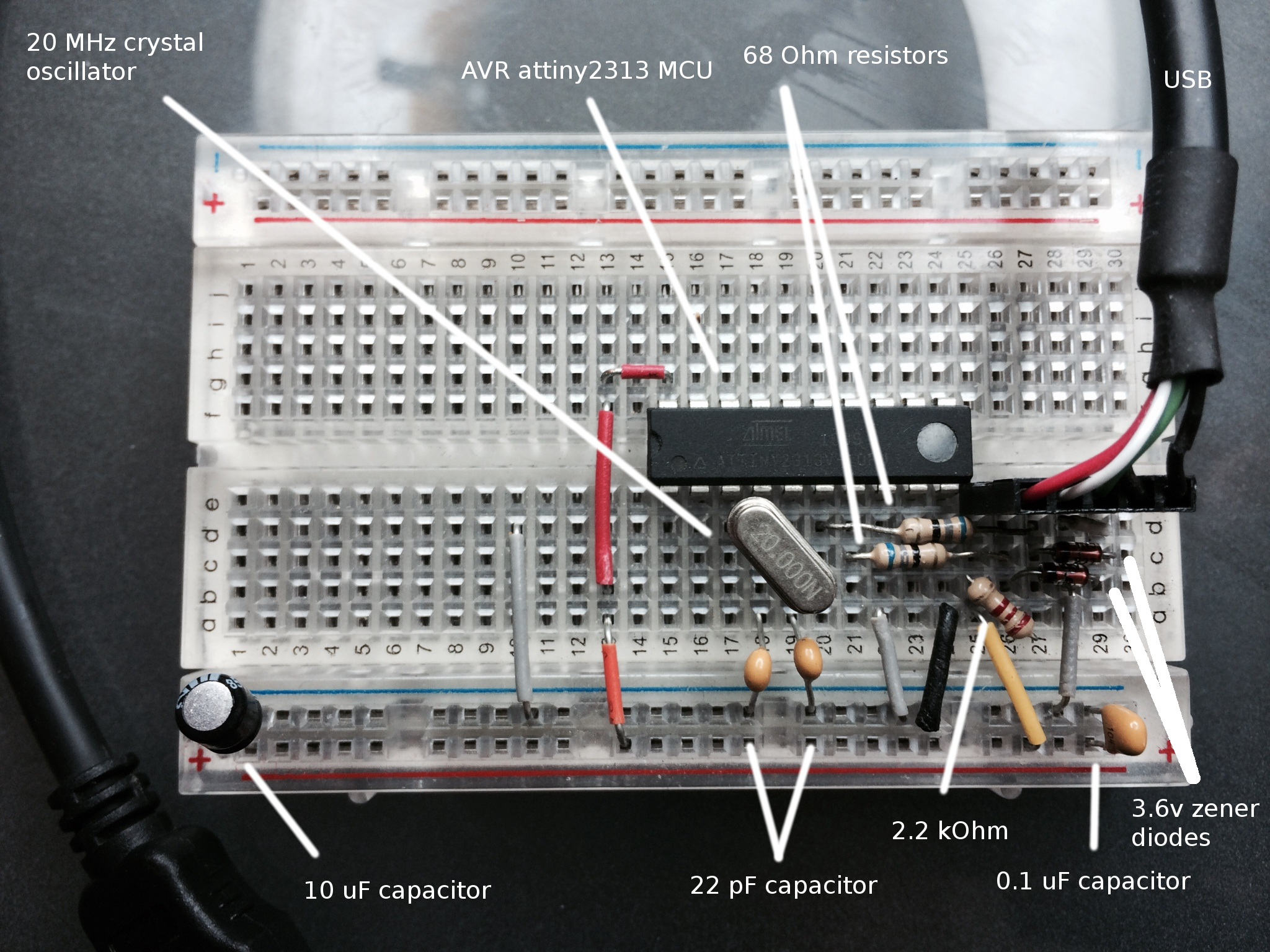
- 20 Mhz crystal between
XTAL1andXTAL2with 22 pF caps going to ground - 2.2 KOhm resistor going from 5v to USB D-
- 2.6v low wattage zener diodes going from D+ and D- to ground (more on this later, this is important)
- 68 Ohm resistor going from D- to
PD3 - 58 Ohm resistor going from D+ to
PD2 - 10 uF cap between 5v and ground
- 0.1 uF cap between power and ground
One important thing to think about is that USB data lines are by specification operated at 3.3v, while the AVR is typically powered at 5v. There are a couple of common ways of handling this:
powering the AVR itself with 3.3v. Caveat to this is that it is difficult to achieve higher (and V-USB supported) clock rates. For this reason, I did not go this route.
Using a voltage regulator. I did not go this route for 2 reasons: they are bulky, and they are relatively expensive.
Zener diodes, which is used here. I thought this was the best route to go. They are cheap, and they are pretty cool. Read up on them.
Now that your circuit is set up, we can dig into the firmware. I had a project setup that looked something like this:
    project/
        main.c
        usbrequests.h
        usbdrv/
You should set yours up to be similar. The usbdrv directory is a direct extract from V-USB (download here).
Configuring V-USB
All changes necessary in usbdrv are contained in usbdrv/usbconfig.h, and most of the defaults can be used. We will only be changing a few things.
First, set the port that V-USB will use to D:
#define USB_CFG_IOPORTNAME D
Set the pins for PORTD respectively (reminder above in the circuit explanation):
#define USB_CFG_DMINUS_BIT      3
#define USB_CFG_DPLUS_BIT       2
We are going to have the USB host power our device:
#define USB_CFG_IS_SELF_POWERED 0
You can set the vendor name and device name to whatever you'd like. Here is what I used:
#define USB_CFG_VENDOR_NAME     'N', 'i', 'k', ' ', 'H', 'a', 'r', 'r', 'i', 's'
#define USB_CFG_VENDOR_NAME_LEN 10

#define USB_CFG_DEVICE_NAME     'u', 's', 'b', 'r', 'e', 'm', 'o', 't', 'e'
#define USB_CFG_DEVICE_NAME_LEN 9
Entrypoint
Now that we are done configuring V-USB, we can move on to actually implementing it. The bare minimum to get this working is, well, bare.
You start with a call to usbInit():
usbInit();
usbDeviceDisconnect();
The V-USB documentation recommends a delay before calling the connect function, so we will do that:
int t;
for(t = 0; t < 250; t++) {
    wdt_reset();
    _delay_ms(2);
}
Then we call connect, enable interrupts, and add our usb poll loop. The usbPoll() method should be called every 250ms at the least.
usbDeviceConnect();
sei();

while(1) {
    wdt_reset();
    usbPoll();
}
That's it. Your overall main method could look something like this:
int main(void)
{
    wdt_enable(WDTO_1S);
    usbInit();
    usbDeviceDisconnect();

    int t;
    for(t = 0; t < 250; t++) {
        wdt_reset();
        _delay_ms(2);
    }

    usbDeviceConnect();
    sei();

    while(1) {
        wdt_reset();
        usbPoll();
    }

}
This is as bare of an implementation as it gets. In a later post I'll add how to do communication between your USB device and a host driver.
When you plug in your USB device you should see something similar to this in dmesg:
[2763204.970775] usb 1-1.6: new low-speed USB device number 126 using ehci-pci
[2763205.069196] usb 1-1.6: New USB device found, idVendor=16c0, idProduct=05dc
[2763205.069201] usb 1-1.6: New USB device strings: Mfr=1, Product=2, SerialNumber=0
[2763205.069204] usb 1-1.6: Product: usbremote
[2763205.069206] usb 1-1.6: Manufacturer: Nik Harris
Yay, we're done.