For the past couple of weekends I've been working on a side project called Doorman, which enables RFID entry for my apartment. The hardware connected to the physical door will be communicating wirelessly with the server controller using a pair of Digi XBee radio modules. The programming interface for the XBee modules is Universal Asynchronous Receiver/Transmitter (UART), a common piece of hardware used to send and receive data. In this case, it is being used to send and receive data to and from the XBee and the ATMega328P.
Given the prevalence of UART, the ATMega328P has builtin circuitry for enabling UART communication. Below is a block diagram of the UART circuitry, courtesy of the datasheet for the ATMega.
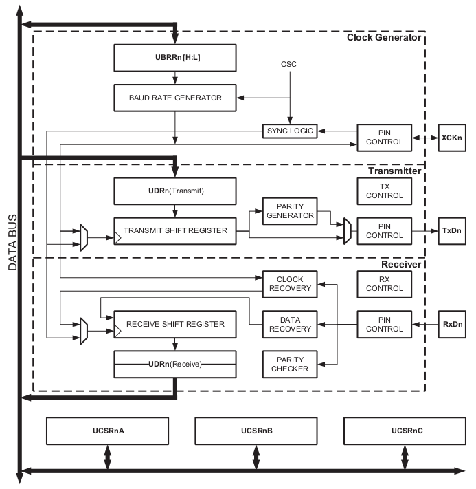
Enabling and initializing the UART circuit on the MCU is straight forward, and the data sheet even provides the formulas for calculating UBBR (for baud rate) as well as sample code for initializing and using UART. In the most basic implementation, there are three steps that need to be taken to get UART ready for use:
Set USART baud rate register (UBRR) to reflect our baud prescaler, which is used for clock generation.
Enable receiver and transmitter
Set frame format to 8 data bits,
As covered above, the datasheet gives us the formula needed to calculate this prescaler in asynchronous normal mode:
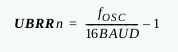
fOSC being the CPU speed in hertz, and the intended baud rate. In my case, the fuse settings I've configured on the ATMega328P sets the oscillaor to 8 MHz (no divide by 8).
Steps two and three are easy as well, by setting the appropriate bits in the UCSRB and UCSRC registers:
UCSR0B = (1<<RXEN0)|(1<<TXEN0);
UCSR0C = (1 << UCSZ01) | (1 << UCSZ00);
At this point, as long as your circuit is hooked up properly, you're ready to start send and receiving data. Here is the basic pinout for the ATMega328P and XBee:
- MCU TX PD1 to XBee DIN
- MCU RX PD0 to XBee DOUT
I used the XBee XCTU software to generate a testing byte array containing an XBee API frame that would transmit at test packet. Every 1 second, the ATMega328P would send this test packet to the XBee connected over UART. Then the XBee would transmit this to another XBee I have connected to my computer.
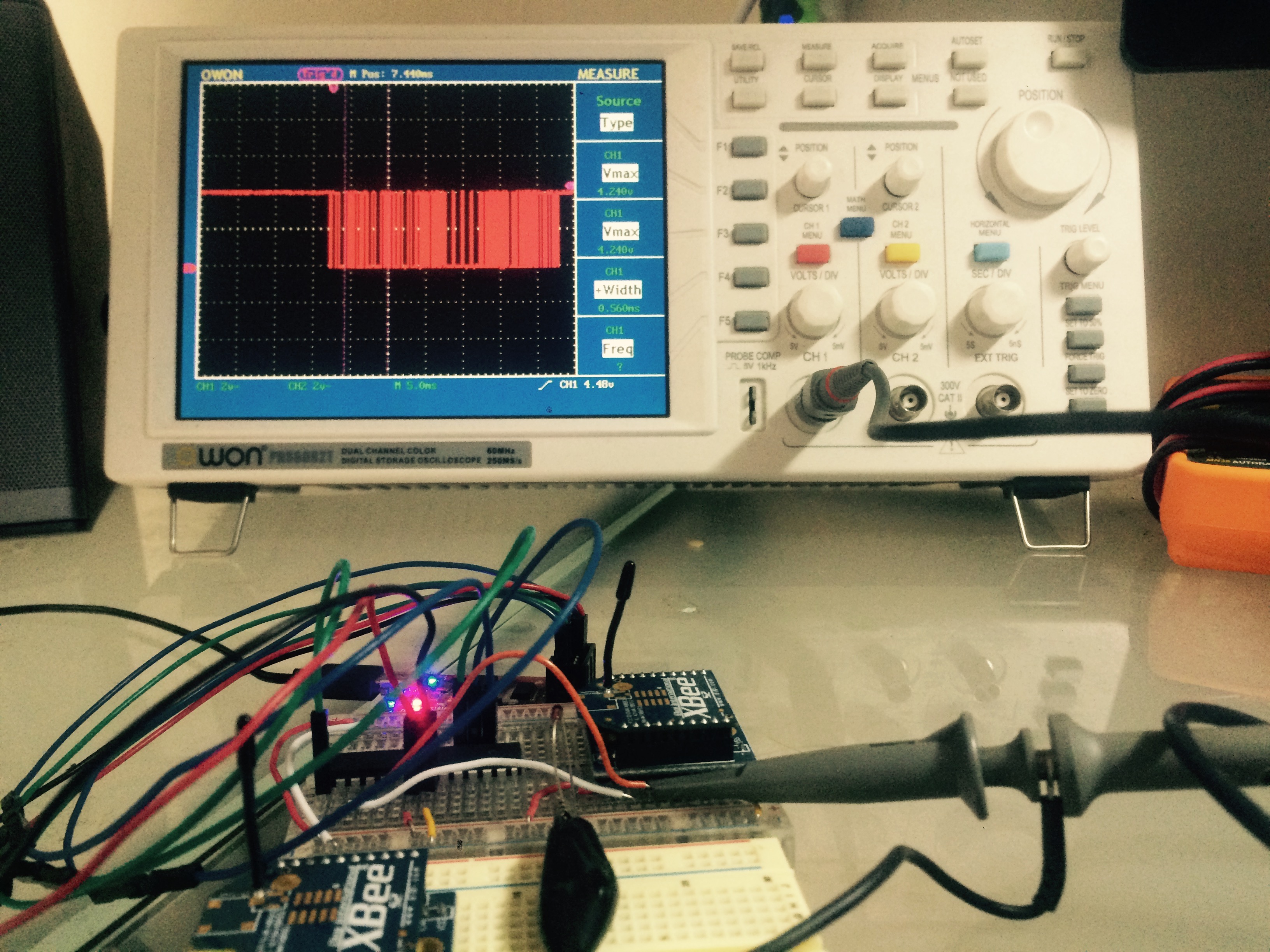
This is where things get tricky. Unfortunately, the XBee connected to my computer wasn't receiving the test packets from the ATMega328P. Since I generated the test packet using the XBee software, the probability of an error in the API frame was pretty small. My first thought was that something was up with UART, so I hooked up a probe from an oscilloscope to the TX pin on the ATMega, and clearly I could see clean waveforms, and the same waveform being transmittd every second.
I unhooked the XBee from the ATMega328P and wired it straight to an FTDI chip on my computer so I could see exactly what was being sent over UART. I changed the byte array from the test API frame to a simple string of characters: "this is a test.\n"
What I was seeing wasn't pretty. Most of the sentence was in tact, but what appeared to be random bytes were sporadically replacing the bytes that were expected. I replaced the sentence with a single character to be transmitted every second, and to my surprise it was working fine. It appeared that as long as I was transmitting slowly enough, everything worked fine. I ended up finding that a 10ms delay between each transmit allows everything to function perfectly. Very odd.
I double checked the fOSC definition and the baud rate and triple checked that I was calculating the UBRR value properly. Everything looks right. I've never had breadboard capacitance be an issue, even at higher clock speeds, so that isn't on my radar.
All in all, it turns out the internal oscillator is not very accurate. I didn't check the datasheet for the threshold, but swapping out with an external crystal oscillator does the trick. All is well.
The internal oscillator just isn't great -- lesson learned.